Linear Circuit Analysis
1. Introduction
2. Basic Concepts
- Charge, current, and voltage
- Power and energy
- Linear circuits
- Linear components
- Nodes and loops
- Series and parallel
- R, L & C combinations
- V & I combinations
3. Simple Circuits
- Ohm's law
- Kirchhoff's current law
- Kirchhoff's voltage law
- Single loop circuits
- Single node-pair circuits
- Voltage division
- Current division
4. Nodal and Mesh Analysis (DC)
5. Additional Analysis Techniques (DC)
- Superposition
- Source transformation
- The $V_{test}/I_{test}$ method
- Norton equivalent
- Thévenin equivalent
- Max power transfer
- Summary
6. AC Analysis
7. Magnetically Coupled Circuits
8. Polyphase Systems
9. Operational Amplifiers
10. Laplace Transforms
11. Time-Dependent Circuits
- Introduction
- Inductors and capacitors
- First-order transients
- Nodal analysis
- Mesh analysis
- Laplace transforms
- Additional techniques
12. Two-Port Networks
Appendix
Electric Charge ($Q$)

Electric charge is a concept rigorously defined in electrostatics in terms of the properties matter exhibits when placed in an electromagnetic field. In the context of electric circuits, we are interested in the charge flowing through wires (or entering or leaving the terminal of a component). This charge equals the number of electrons passing through the wire ($N$) multiplied by the charge of a single electron ($-q$), where $q$ is the elementary charge: $$\begin{equation}q=1.602\times10^{-19}\:{\class{mjunit}C}\end{equation}$$
The SI unit of charge is the coulomb (${\class{mjunit}C}$). The name comes from the French physicist Charles-Augustin de Coulomb (1736–1806), who is best known for formulating Coulomb’s law, which describes the electrostatic force between two point charges $Q_1$ and $Q_2$: $$\begin{equation}F=\frac{1}{4\pi\epsilon_0} \cdot \frac{Q_1 Q_2}{r^2}\end{equation}$$ where $\epsilon_0$ is the electric permittivity of vacuum and $r$ is the distance between the two charges.
Electric Current ($I$)

The electric current going through a wire is defined as the charge that goes through that wire in unit time $$\begin{equation}I(t)=\frac{dQ}{dt}\end{equation}$$ The SI unit of electric current is the ampere or amp (${\class{mjunit}A}$). The conventional symbol for current is $I$ (see Fig. 1), which originates from the French phrase intensité du courant, (current intensity). The $I$ symbol was first used by André-Marie Ampère (1775–1836), after whom the unit of electric current is named.
The current can flow in either of the two directions in a wire. When defining a variable $I$ to represent the current, the direction representing positive current must be specified, usually by an arrow on the wire. This is the reference direction of the current. The actual direction of current through a specific circuit element is usually unknown until the current is computed numerically or measured experimentally. Consequently, the reference directions of the currents are often assigned arbitrarily when we start analyzing a circuit. After the circuit is solved, a negative value for the current implies that the actual direction of the current is opposite than that of the reference direction.
If the current is known, one can compute the total charge that goes through the wire from time $t=0$ to $T$ by integrating the previous equation $$\begin{equation}Q(T)=\int_{0}^T I(t) dt\end{equation}$$
Electric Potential and Voltage ($V$)

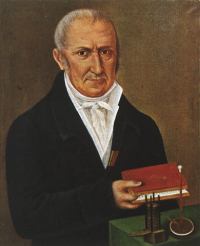
The electric potential, also known as electrostatic potential (or simply potential), is defined as the amount of work required to move a unit charge from a reference point (often taken at infinity) to a specified point. In electric circuit analysis, the reference point is conventionally chosen as the ground node, whose potential is assumed to be zero. The SI unit of electric potential is the volt (${\class{mjunit}V}$). The name comes from the Italian physicist Alessandro Volta (1745–1827), who invented the first chemical battery, known as the Voltaic pile.
Ideal wires are defined as wires with zero internal resistance. Therefore, the amount of work to move electrons from one point of an wire to another point of the same wire is equal to $0$. In addition, the electric potential of an ideal wire is the same at any point on the wire.
Voltage, also known as (electric) potential difference, is the difference of the electric potential between two points. Therefore, the SI unit of the voltage is the same as for electric potential, the volt. If we denote the two points by $A$ and $B$ and the potentials at those two points by $V_A$ and $V_B$, the voltage between the two points is $$\begin{equation}V_{AB}=V_{A}-V_{B}\end{equation}$$ To simplify the notations on circuit diagrams, we often denote point $A$ (the first point) with $+$ and point $B$ (the second point) with $-$ (see Fig. 1). In this case, voltage $V$ is understood to be the voltage from the node denoted with $+$ to the node denoted with $-$.
Finally, using the previous equation it is obvious that $$\begin{equation}V_{AB}=-V_{BA}\end{equation}$$
Examples of Solved Problems
-
Analytical
Compute current when charge is given analytically
Compute charge when current is given analytically
-
Graphical
Compute current when charge is given graphically (4 intervals)
Compute charge when current is given graphically (5 intervals)
Compute current when charge is given graphically (7 intervals)
Compute charge when current is given graphically (7 intervals)
-
Analytical
Compute current when charge is given analytically
Compute charge when current is given analytically
Compute charge or current entering a box analytically
-
Graphical
Compute current when charge is given graphically (2 intervals)
Compute current when charge is given graphically (3 intervals)
Compute current when charge is given graphically (4 intervals)
Compute current when charge is given graphically (5 intervals)
Compute current when charge is given graphically (6 intervals)
Compute current when charge is given graphically (7 intervals)
Compute charge when current is given graphically (2 intervals)
Compute charge when current is given graphically (3 intervals)
Compute charge when current is given graphically (4 intervals)
Compute charge when current is given graphically (5 intervals)
Compute charge when current is given graphically (6 intervals)
Compute charge when current is given graphically (7 intervals)
Compute charge or current entering a box graphically (2 intervals)
Compute charge or current entering a box graphically (3 intervals)
Compute charge or current entering a box graphically (4 intervals)
Compute charge or current entering a box graphically (5 intervals)
Compute charge or current entering a box graphically (6 intervals)
Compute charge or current entering a box graphically (7 intervals)
See also
Read more
Charge
Charles-Augustin de Coulomb
Unit, C
Electric charge
Current
André-Marie Ampère
Unit, A
Electric current
Voltage
Alessandro Volta
Unit, V
Voltage